The Ins and Outs of USB Gen 3 and Type-C™
By Jon Gabay for Mouser Electronics
Usually, when a new version of an existing standard is released, some jump on the bandwagon with both feet, while
some wait on the sidelines to see how the masses accept the new. Just because something is new, doesn't mean it is
better - or cost-effective for manufacturers to adopt. It also doesn't mean that users will want it, need it, or
want to pay extra for it.
USB Type-C is one of these 'new and improved' standards that potentially can provide many benefits to some users,
but also carries with it some confusion for end-users, designers, and manufacturers. From a square-one perspective,
the third generation of USB (Gen 3.x) has yielded USB 3.0 and 3.1 gen 1 and 2 that can use a Type-C, "flippable"
connector scheme. This allows users to plug in either way without the annoying polarity limitation of the present
D-shell style USB connectors.
However, confusion abounds because the new 24-pin flippable connector features pins that can be repurposed, and
includes active communications to the PCB mounted connector for setup and configuration. This can complicate
enumeration, identification, and proper mode selections as equipment is plugged in. It also means more overhead for
firmware with both computers and peripherals.
"Buyer beware" is in effect. There are cables manufactured that claim USB Gen 3.x functionality but in reality are
not able to access the high speed and power modes or all the features and functionality the updated specifications
have to offer. This article looks at USB Gen 3.x and the Type-C connection scheme to shine some light on the
problems, issues, and possible solutions needed to allow manufacturers and users to understand and take advantages
of this somewhat confusing standard.
Serial Advantages
Serial busses have historically evolved to the point of making parallel busses unnecessary. It used to be common
thinking that when performance was necessary, a parallel bus was the only way to go. From Centronics printer ports
to SCSI hard drive standards, these were thought of as the highest speed techniques once upon a time.
But several factors were in play against parallel connectivity. Reliability is inversely proportional to the number
of connections and reliability can be an issue, especially with wider bus-width cabling. Also, distance limitations
can come into play, especially with the higher cost of connectors and cabling.
Serial busses, on the other hand, opened the door for terminals and networking, from the first RS-232 Wise and Adds
terminals, to Ethernet, and fiber optics. The benefits of serial communication have proven themselves repeatedly for
computer connectivity.
Likewise, since the first introduction of the Comm-Plex serial port coprocessor, through Apple's Appletalk and
Firewire, and up through modern day USB, serial communications has proven itself as a reliable and cost-effective
technique for peripheral connectivity.
USB 2.0 Onward
The Type-C is slated to replace the existing USB Type-A and Type-B polarized connectors with what they call a
future-proof style connector that should handle any future enhancements. Either Type-C connector on a cable assembly
will connect to either a host or a device. Sounds good on paper, but in practice, there may be some wrinkles to iron
out.
Legacy USB 2.0 uses a single polarized 5V supply to power relatively low-powered peripherals. USB Gen 3.x using the
Type-C connector, on the other hand, provides four power/ground pairs. This is perhaps the biggest head turner when
it comes to looking at USB Gen 3.x Type-C.
The single 5V USB 2.0 typically could supply 500 mA, or around 2.5 W. When USB 3.0 upped this to 1.5 A, it was not
much of attention grabber. True, 7.5 W is greater, but some specialty USB 2.0 devices like mobile hotspots had
already been supplying over 2 (or over 10 W) because their specialty devices and connectors required more power.
The change from a simple 4 wire cable of USB 2.0 to the 24 pin cables of Gen 3.x specifications is significant. The
unisex connector affixed on both ends of the cables will allow easier connection in the dark - or after a full night
of excessive partying. But with benefits also come some limitations. However, the benefits had better be worth the
limitations to propel the 'new and improved' versions.
The real game changer is the 100W that the USB Type-C connector is slated to handle when implementing USB-PD. This
is more than enough for cell phones and tablets and can even be used to charge laptops. It may spawn an entirely new
spectrum of mobile and transportable peripherals that can leverage the higher amount of power available.
It is evident that the USB-PD, USB Gen 3.1 and Type-C specifications represent a significant leap forward for
device makers, equipment makers, and end users alike (Fig. 1). In a world where Keep It Simple Stupid (KISS) is a
philosophy many try to live by, it may seem this much more complicated implementation of what was once thought to be
a straightforward and easy-to-use and implement interface.
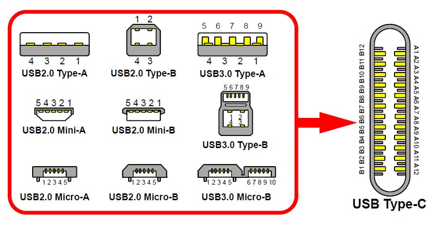
Figure 1. The many permutations of USB have mostly been form factor changes to a 4- or 5-pin
interface. USB 3.0 deviated from this with 10-pins and Type-C pushes this to 24-pins. (Source:
Microchip)
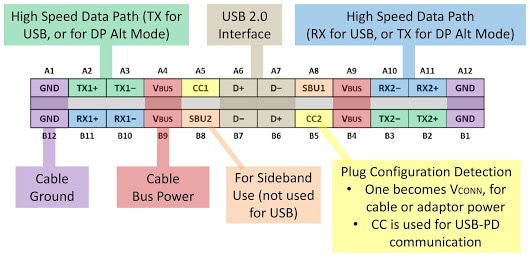
Figure 2. The flippable 24-pin USB Type-C connector has a certain symmetry and dedicated pins to
detect orientation to configure the differential transmit and receive lines as well as the configuration lines and
the redundant USB 2.0 compatible pins. Note the power and ground pins always remain at the same position no matter
which way the connector is plugged in. (Source:
Bensen Leung on
Google+)
The 24-pin, flippable Type-C connector is about the same size as the USB Type-B micro connector and measures 8.4 x
2.6mm. However, each 5V Vbus power signal is capable of supplying up to 5A, resulting in the higher 100W rating. A
key benefit with Type-C USB 3.x Gen 2 standard is that cables will be uniform. There will no longer be a large
polarized end and a small polarized end. The volume of USB Type-C connectors will double, in fact, and these cable
connectors especially need discounts that come with economies of scale since there are many more pins to connect
with Type-C (which drives costs up.)
Thicker quality metal wires in USB-PD-capable cables that are rated at the highest level are needed to pass this
power. In turn, you will need a higher quality of wires to pass the higher speed differential signals for 10Gbps
modes. Moreover, buyer beware: all USB 3.1 cables are not created equal. So much confusion and misrepresentation
have taken place as several manufacturers have made mistakes in the rush to get the product out to market. Buying
USB Type-C cables from well-known manufacturers at an authorized distributor (one example being Mouser Electronics) will go a long way to protecting
new USB products with Type-C ports.
Even USB 2.0 can use the Type-C connectors for low speed, full speed, and high-speed transfers. But, only the USB
3.1 full-featured Type-C cables can support the 5Gbps SuperSpeed or SuperSpeed 10 Gbps transfer rates.
The Terminator
Terminating resistors seem to be a source of confusion and problems for some cable and equipment makers. A single
resistor on both CC lines will cause your active, e-marked cables fail to charge your devices and make your
equipment think a headphone is plugged in. And headphones are one of the primary applications for USB 3.1 Gen 2 with
Type-C connectors. It may seem counterproductive to replace the simple audio jacks for headphones with a costlier
connection scheme, but already Intel and Samsung have announced their intent to eliminate headphone jacks completely
from their devices and Apple has already done so in the recent release of the iPhone 7.
It is Not How Long You Make it; it is How You Make it Long
Cabling limitations will affect power delivery, too. Intermediate Frequency (or IF) cables can only deliver 60W of
power and only deliver 5Gbps data rates. However, a slew of bad cables and chargers are on the market, so it is up
to the consumer to verify the SS or SS+ markings.
Cable makers also need to adhere to the strict voltage drop requirements of the Gen. 3.1 Type-C style connectors
(Fig. 3).
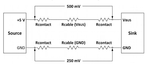
Figure 3. Key is low end to end resistance of both power and ground lines. This is one of the
limiting factors keeping distances to around 1 meter. Eight-foot charge-only cables may not be feasible with the
Type C connectors as they are with USB 2.0 versions. (Source:
Bensen Leung on
Google+)
Only 250mV can be present on the ground connections with only a 500mV drop on the positive supply lines. This is
one reason that the Type-C connectors and cables will be limited to roughly three-foot lengths and, this depends on
upon manufacturers using quality connectors, wire, and contacts.
Data Transfer is Key
While USB 2.0 transfer speeds were an amazing 480Mbps when first introduced, USB 3.1 ups this to 5Gbps and 10Gbps,
depending on the modes, cables, and equipment. This >20 times increase in speed will open the door for new and
improved types of devices and peripheral including holographic display systems. Intel has thrown support behind USB
3.1 Type-C for 4K video Thunderbolt applications.
Four differential signaling pairs are used to accomplish these high data rates; two pairs for TX data and two pairs
for RX data, allowing full duplex full speed communications. USB 3.1 Gen 2 also uses a new encoding scheme
(128b/132b) which reduces communications overhead to only three percent. There are also two new sideband signals for
auxiliary communications, as well as CC, CC1, and CC2 configuration lines which can be used by connected equipment
to determine modes of operation, power level, and speed.
The CC signals are active communications to the connector that allow the connectors to be set up for the right
modes, power schemes, and data rates. Sideband and configuration channel pins are dedicated to helping control and
detect the orientation of the flippable connector. Color coding schemes have also been defined to help identify and
implement this potentially confusing version of what was once a simple 4-wire communications bus (Fig. 4).

Figure 4. Color coding of signals for data and power will make designers jobs easier, especially
for debugging purposes. (Source:
Wikipedia)
Designing for USB 3.1 Gen 2
Designers will need to have accurate information and well-engineered parts to design compatible equipment that
conforms to standards accurately and successfully. Fortunately, many manufacturers are stepping up to the plate to
provide quality components, tutorials, development kits, and reference designs. Cypress Semiconductor offers several reference designs
illustrating charging, power delivery, cable interfacing, and even HDMI interfacing.
Of equal importance are the connectors themselves. The Amphenol MUSBR Rugged USB Type-C Connectors are a
prime example of the solid through-hole style, vertical and right angle flippable Type-C connectors that OEMs can
place on their boards. These ruggedized Type-C connectors use a sealing technique that exceeds IP67 to ensure reliable
performance for handheld and portable equipment.
Molex
offers connectors for USB Type-C with its 105450-0101
female and 105444-0001 male connectors, and cable assemblies. Other connector companies including Hirose,TE Connectivity, and JAE Electronics also provide a wide
range of Type-C (Fig. 5).
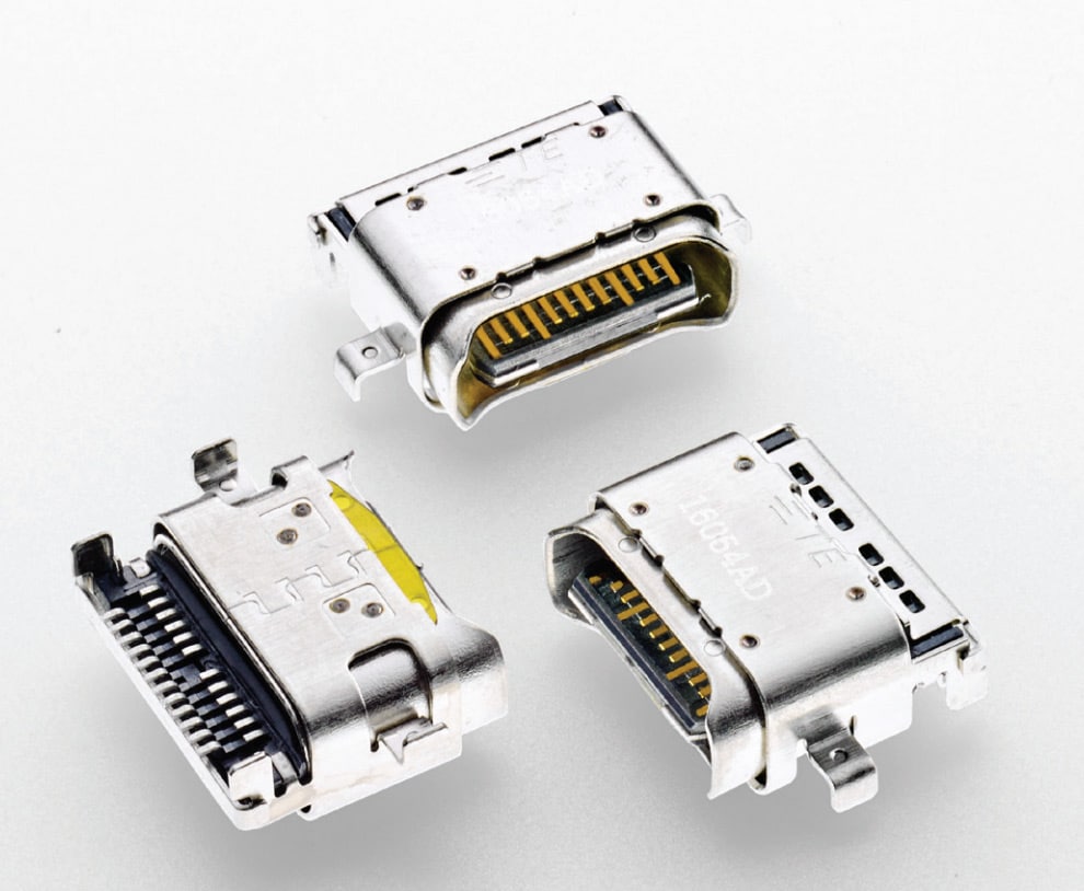
Text Box: Figure 5. Splash-proof Type-C connectors
(e.g., P/N 2295018-2) are ready to populate boards with both vertical and right angle configurations. (Source: TE
Connectivity)
From a semiconductor perspective, several pieces of the puzzle need to be in place to implement a quality design.
Controller chips are perhaps the most complex devices that must adhere to the evolving specifications evolve. Texas Instruments' TUSB320 controller, for example,
unburdens designers from the configuration aspects of USB 3.1, supporting both upstream and downstream modes.
TI also offers the HD3SS2522RHUR
USB Type-C mux, controller, and interface device which supports the full 10Gbps SuperSpeed+ data rates. Note the low
600µA supply current, ideal for battery-powered devices. Master side controllers and hubs will also need
independent Type-C and power delivery like the TI TPS65982ABZQZR two-port power
controller for USB 3.1 Gen 2 Type-C interfaces.
Fairchild Semiconductor's FUSB340TMX is a 5Gbps, 2x2:1,
USB 3.1 switch. Two differential pairs operate individually and at 5Gbps even in the SuperSpeed+ modes to provide
the full 10Gbps bandwidth. This means that equipment, hubs, and aggregators can take advantage of the small-sized
(2mm x 2.8mm), 10GHz-bandwidth, high-speed switch. Power consumption is 1/10 of the "nearest competitive solution"
and packages are up to 43% smaller.
Unplugging it All
Altogether, there are 24 connection points in this new cabling scheme, representing a significant change from the
4-wire cables with which we are familiar. Any engineer will tell you that the number of connections is inversely
proportional to reliability, so 24 connection points can cause angst. The new 24-pin connectors are also physically
smaller than the existing 4-pin USB connectors with openings at ~8.4mm x 2.6mm. At present, cable lengths of one
meter seem to be the limitation for higher speed and power standards.
However, quality cable-, device-, and connector-makers are ready to step up to the plate with well-engineered
components that cell phone, laptop, and other equipment makers are eagerly seeking. Expect clever solutions to
emerge as more manufacturers understand and embrace the USB Gen 3.1 Type-C standard.
How well the public will respond is another matter. Time will tell if USB 3.1 and Type-C cabling will make the
connection.
 After completing his studies in electrical
engineering, Jon Gabay has worked with defense, commercial, industrial, consumer, energy, and medical companies as a
design engineer, firmware coder, system designer, research scientist, and product developer. As an alternative
energy researcher and inventor, he has been involved with automation technology since he founded and ran Dedicated
Devices Corp. up until 2004. Since then, he has been doing research and development, writing articles, and
developing technologies for next-generation engineers and students.
After completing his studies in electrical
engineering, Jon Gabay has worked with defense, commercial, industrial, consumer, energy, and medical companies as a
design engineer, firmware coder, system designer, research scientist, and product developer. As an alternative
energy researcher and inventor, he has been involved with automation technology since he founded and ran Dedicated
Devices Corp. up until 2004. Since then, he has been doing research and development, writing articles, and
developing technologies for next-generation engineers and students.


